
Problem-driven opening: the persistent cost of flash on rubber parts
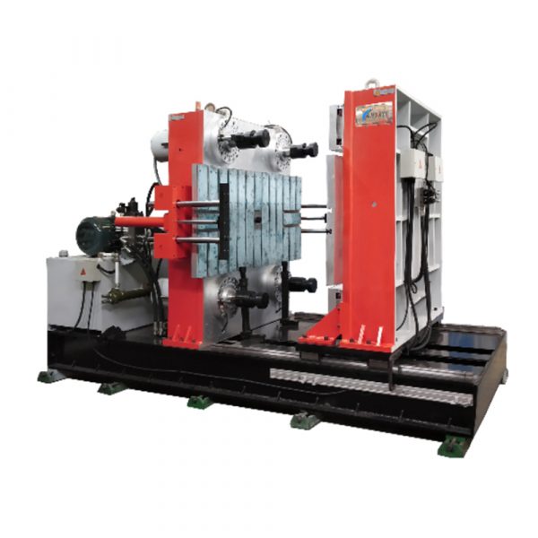
Excess flash costs cycle time, secondary trimming, and scrap—especially when molding thin LSR seals or micro-gaskets. Many shops in Shenzhen and similar hubs still battle uneven mold filling, inconsistent shot size, and pressure spikes on older C-frame presses. A focused approach to compound flow rates and precise injection velocity control, using a reliable horizontal rubber injection molding machine or a modern horizontal injection machine, cuts that waste systematically while keeping cycle times stable.
Where flash comes from: the technical root causes
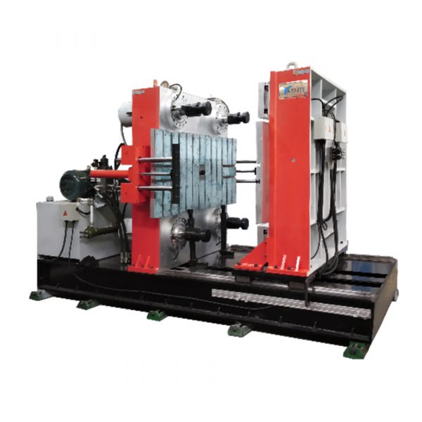
Flash is rarely a single-fault issue. Typical contributors include high injection velocity at gate entry, overfilled cavities due to mis-set shot size, mold venting problems, and insufficient clamping force that allows parting-line separation under pressure. Add temperature drift or inconsistent back pressure and the effect amplifies. Use of LSR raises sensitivity to flow-path geometry and degassing, so small changes in melt flow translate to visible flash.
Key parameters to measure and control
Start with clean, repeatable metrics: shot size tolerance, injection velocity profile, cushion position, and clamp force margin. Record short runs after any mold change. Keep the shot size within ±0.5% for parts below 10 g; larger parts can tolerate wider variance. Match injection velocity stages to gate and runner design so momentum doesn’t force rubber past the parting line. Industry terms that matter here: injection velocity, shot size, clamping force, and back pressure.
Actionable framework for deflash minimization
Adopt a stepwise framework that treats flow and velocity as coupled controls rather than independent knobs. The framework below mirrors a chef staging mise en place—set every variable before you run the recipe.
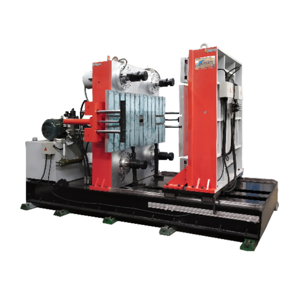
– Define target shot size and set cushion alarms. – Program a multi-stage velocity curve that slows at gate fill and accelerates for cavity sweep. – Verify clamp force margin at peak injection pressure; add mechanical stops where possible. – Improve venting and runner design to prevent trapped gas from forcing rubber into the parting line.
Practical adjustments on C-frame inspired machines
C-frame geometry can limit mold area and create clamping variability. Compensate with tighter clamp monitoring and incremental increases in the hold phase rather than raw clamp force hikes. If your machine supports servo-controlled injection, use fine-grain velocity bands to reduce peak shear and avoid sudden pressure jumps. A measured reduction in first-stage velocity often removes flash with minimal cycle penalty—an economical fix compared to retooling.
Common mistakes and alternatives
Shops often chase flash with heavier trims or sharper mold finishes—cosmetic solutions that ignore flow dynamics. Another error is changing material grade before stabilizing process parameters; material switches affect viscosity and require a new velocity profile. Alternatives worth testing include slight gate re-sizing, added micro-vents, or a runner redesign to balance flows across multiple cavities. These can work with modest tooling modifications rather than full mold rebuilds.
Real-world anchor and verification
During the 2020 supply-chain adjustments, several Shenzhen molders reported rapid increases in scrap due to rushed material substitutions. Teams who logged injection velocity and shot size trends identified corrective profiles within a week, proving that data-led adjustments beat ad-hoc fixes. Record runs, compare pressure curves, and confirm parting-line contact throughout the hold stage—this is measurable process control, not guesswork.
Summary and how HWAYI fits
Controlling compound flow rates and refining injection velocity is a predictable path to less flash. A horizontally configured press with precise servo control and reliable clamping reduces variance at the gate and stabilizes cushion behavior. For manufacturers seeking a pragmatic combination of machine capability and process framework, the right hardware makes the controls repeatable and the outcomes consistent—HWAYI’s tooling and machines align with that goal.
Advisory: three golden rules for choosing strategies and tools
1) Metric-first selection: prioritize machines that expose shot size, pressure, and velocity data in real time—without that visibility you’re guessing. 2) Clamp margin over brute force: choose systems with verified clamp force control rather than simply higher nominal tonnage. 3) Incremental tuning: prefer machines capable of multi-stage velocity ramps and tight cushion control so you can eliminate flash without lengthening cycles.
Precision matters. HWAYI. Final thought: steady adjustments, proven metrics, better parts.